Page 9 - WENZHOU ZHUOCHAO ELECTRIC CO.,LTD.
P. 9

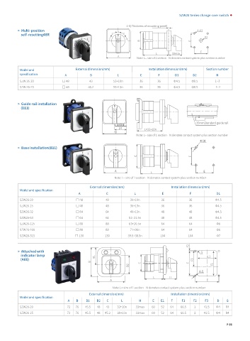
SZW26 Series change-over switch


                                                             1-5( Thickness of mounting panel)
          >  Multi-position                              0                                     4-D1
              self-resetting48R                       1     3
                                                                                                  D2
                                                     2       4
                                                                    B                       E
                                                                                                F
                                                                           L       33max
                                                         A
                                                                  Note: L= size of 1 section    N denotes contact system plus section number
          Model and                  External dimension(mm)             Installation dimension(mm)  Section number
          specification
                                A           B            L          E       F       D1       D2         N
          SZW 26-20            □ 48         43         53+10n      36       36      Φ4.5    Φ8.5       1~3
          SZW 26-25            □ 48        45.2        55+13n      36       36      Φ4.5    Φ8.5        1~2


          >  Guide rail installation
              (D11)


                                                                                               35mmStandard guide rail
                                                          24
                                                                      L=32+10n
                                                       48
                                                                  Note: L= size of 1 section    N denotes contact system plus section number
                                                                                                4-D1
          >  Base installation(B11)
                                                                  C                         F


                                                        A                                         E
                                                                         L
                                                        Note: L= size of 1 section    N denotes contact system plus section number

                                            External dimension(mm)                 Installation dimension(mm)
          Model and specification
                                      A             C            L            E            F            D1
          SZW26-20                   □ 48          48          30+10n         36           36           Φ4.5
          SZW26-25                   □ 48          48          36+13n         36           36           Φ4.5
          SZW26-32                   □ 64          64          40+13n         48           48           Φ4.5
          SZW26-63                   □ 64          64         51+21.5n        48           48           Φ4.5
          SZW26-125                  □ 88          88         63+26.5n        64           64           Φ6
          SZW26-160                  □ 88          88          71+36n         64           64           Φ6
          SZW26-315                  □ 130         130        39.5+38.5n     104           104          Φ7
                                                                                           F2
          >  Attached with                                                                       G
              indicator lamp                  B1                                                    E1
             (A66)                                                                           F3
                                            B                       C                      F
                                                              B2                                      F1
                                                                                                4-D
                                                                          L       H
                                                     A                                             E
                                                       Note: L= size of 1 section    N denotes contact system plus section number
                                            External dimension(mm)                Installation dimension(mm)
          Model and specification
                                 A   B    B1   B2   C      L       H      E   E1  F     F1   F2    F3   D    G
          SZW26-20               72  76   45.5  48  43   32+10n   33max  60   52  64   66.5   2   41.5  Φ4   R4
          SZW26-25               72  76   45.5  48  45.2  38+13n  33max  60   52  64   66.5   2   41.5  Φ4   R4


                                                                                                             P 05
   4   5   6   7   8   9   10   11   12   13   14