Page 38 - WENZHOU ZHUOCHAO ELECTRIC CO.,LTD.
P. 38

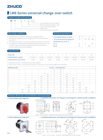
LW6 Series universal change-over switch

          Product model and meaning

             LW      6        -     □       /       □
                                               Contact diagram serial number
                                               Positioning characteristic code
                                               Contact terminal number
                                               Design code
                                               Universal change-over switch
          Operating conditions                                 Technical parameters
          1、The altitude of installation site does not exceed 1000m;
                                                               Conventional heating current Ith                        A  5
          2、Ambient air temperature is not higher than 40℃ and not lower
                                                               Conventional operating voltage  Ue                   V  220     250      380
               than -30℃ .
          3、Air relative humidity is no more than 85% (equivalent to 20±5℃ ).  Rated operating current   Ie
          4、It is applied to the media that are kept away from explosion, and   AC-15                                                                              A  1.5                 0.95
               contain no gas and dust(including conductive dust) that can
                                                               DC-13                                                                             A  0.55
               corrode metal and destroy insulation.
          Classification

          Model LW6-                   1         2        3         4        5         6         8        10
          Contact terminal number   1 Section  2 Section  3 Section  4 Section  5 Section  6 Section  8 Section  10 Section
          Contact terminal pair number  3 Pairs  6 Pairs  9 Pairs  12 Pairs  15 Pairs  18 Pairs  24 Pairs  30 Pairs
         1、Classify by handle’s located position, see Table 2;
         2、Refer to the contact terminal state of switch’s different circuit (Serial numbers are omitted.).
          Positioning code                                Handle’s located position
          A                                                    0°     30°
          B                                                    0°     30°
          C                                            30°     0°     30°    60°
          D                                     60°    30°     0°     30°    60°
          E                                     60°    30°     0°     30°    60°     90°
          F                              90°    60°    30°     0°     30°    60°     90°
          G                              90°    60°    30°     0°     30°    60°     90°    120°
          H                      120°    90°    60°    30°     0°     30°    60°     90°    120°
          I                      120°    90°    60°    30°     0°     30°    60°     90°    120°   150°
          J              150°    120     60°    60°    30°     0°     30°    60°     90°    120°   150°
          K              120°    240°    60°    60°    30°     0°     30°    60°     90°    120°   150°    180°

          External dimension and Installation dimension(mm)
                                               >  Installation dimension  See Diagram 2 and Diagram 3  Choose one for installation
          >  External dimension diagram 1
                                          2~10( Thickness
                                          of mounting panel)                                         46
                                                                                      3-Φ4.5
                                                                                            4-Φ4.5
                                                                             120°      120°
                                                                                                            46
                                                                 Φ56
                                             L=38+13N  37Max     □60            Φ10
                                           (section number)                          Φ38             Φ57
                                               Diagram1                         Diagram2           Diagram3
                                          Note: L= size of 1 section    N denotes contact system plus section number
          >  External dimension diagram 4      >  Installation dimension  See Diagram 5 and Diagram 6  Choose one for installation
                                                                                                 4-Φ4.5
                                                                              4-Φ5  3-Φ9
                                             1-5( Thickness of mounting panel)
                                                                           Φ21         Φ38            Φ40
                                                      56                                  44                44


                                             □64.5        L=75+13n  53Max        44                 44
          P 34
                                            Diagram4                            Diagram5          Diagram6
                                                  Note: L= size of 1 section    N denotes contact system plus section number
   33   34   35   36   37   38   39   40   41   42   43