
Page 5 - SGC SwitchGear Company
P. 5
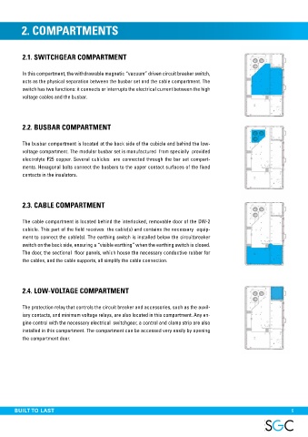
2. COMPARTMENTS


          2.1. SWITCHGEAR COMPARTMENT


          In this compartment, the withdrawable magnetic “vacuum” driven circuit breaker switch,
          acts as the physical separation between the busbar set and the cable compartment. The
          switch has two functions: it connects or interrupts the electrical current between the high
          voltage cables and the busbar.


          2.2. BUSBAR COMPARTMENT


          The busbar compartment is located at the back side of the cubicle and behind the low-
          voltage compartment. The modular busbar set is manufactured  from specially  provided
          electrolyte F25 copper. Several cubicles  are connected through the bar set compart-
          ments. Hexagonal bolts connect the busbars to the upper contact surfaces of the fixed
          contacts in the insulators.


          2.3. CABLE COMPARTMENT


          The cable compartment is located behind the interlocked, removable door of the DW-2
          cubicle. This part of the field receives  the cable(s) and contains the necessary  equip-
          ment to connect the cable(s). The earthing switch is installed below the circuitbreaker
          switch on the back side, ensuring a “visible earthing” when the earthing switch is closed.
          The door, the sectional  floor panels, which house the necessary conductive rubber for
          the cables, and the cable supports, all simplify the cable connection.


          2.4. LOW-VOLTAGE COMPARTMENT


          The protection relay that controls the circuit breaker and accessories, such as the auxil-
          iary contacts, and minimum voltage relays, are also located in this compartment. Any en-
          gine control with the necessary electrical  switchgear, a control and clamp strip are also
          installed in this compartment. The compartment can be accessed very easily by opening
          the compartment door.


 Internal arc fault test, 31.5kA/1s


 THE SPECIALIST IN MEDIUM VOLTAGE SWITCHGEAR  BUILT TO LAST                                                       5