
Page 53 - 通用电气(中国)有限公司
P. 53
EntelliGuard* L
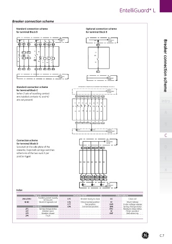
Breaker connection scheme
Standard connection scheme Optional connection scheme
for terminal Block B for terminal Block B
User's User's
LP1 LP4 designated designated
circuits LP5
circuits
B1 B3 B5 B7 B9 B11 B13 B15 B1
57 98 M1
N-RC+ 24V+ 57
- + BAT
SPR N +24- C1 C3 D1 RTC
VDC
N-RC- 24V- 95 M
ML
C4
T C2 D2
58 M2
ST UVR CC 58 Breaker connection scheme
B2 B4 B6 B8 B10 B12 B14 B16
B2
User's
designated User's
circuits designated
circuits
Standard connection scheme STANDARD CONNECTION SCHEME FOR TERMINAL BLOCK C
for terminal Block C User's
designated
(when 3 sets of auxiliary contact circuits
are installed contacts 41 and 42 C1 C3 C5 C7 C9 C11 C13 C15
are not present) Intro
11 21 31 41 13 23 33 43
A
12 22 32 42 14 24 34 44
B
C2 C4 C6 C8 C10 C12 C14 C16
LP2 LP3 User's
designated
circuits
C
Connection scheme User's
designated
for terminal Block D circuits
(Located on the side plate of the D1 D4 D7 D10 D13 D16 D
cassette. Depicted carriage switches
scheme is of the two switch per
position type)
E
X
D3 D6 D9 D12 D15 D18
D2 D5 D8 D11 D14 D17
User's
LP6 LP7 LP8 designated
circuits
Index
Trip unit Indication (ct’d) Abbreviations
24V+/24V- Auxiliary power supply LP5 Breaker ready to close CC Close coil
to trip unit
N-RC Neutral rogowski coil LP6 Disconnected position ST Shunt release
LP7 Test position UVR Under voltage release
Indication LP8 Connected position SPR Spring change status
LP1 Spring charge status RTC Ready to close status
LP2 Breaker open M Motor operator
LP3 Breaker closed BAT Bell alarm trip
LP4 Fault
C.7