
Page 243 - 宁波佳尔灵气动机械有限公司
P. 243
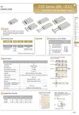
TN• Series TN• Series CXS• Series• (Ø6~Ø32)
We make the difference ISO9001:2008
Double• Rod• Cylinder Double• Rod• Cylinder Twin• Rod• Cylinder/Basic• Type
Overall• Dimension
Cylinder Cylinder
Sizing Sizing
SI TN SI
SI• A. SI• A.
SC• /• SU Ø10 SC• /• SU
SCT SCT
SC• A. SC• A.
SL Features SL
SQ SQ
Double• rod• with• double• force• for• higher •
DNT DNT
anti-bending• and• anti-twisted• strength •
SIB ensured• durable• life• and• perfect• directional • SIB
JDA characteristic. JDA
CQ2 • • • • • • • • • • • • • • • • • • • • • • • • • • • CQ2
CJ2 Ordering• Code Symbol Stroke/Sensor• Switch• Model CJ2
CDU Ø16~Ø25 CDU
TN
TN CXS M 20 100 MT Bore *Sensor• Switch• TN
CXS (mm) Standard• Stroke Model CXS
CXS
(Install by Orbit type)
MGP MGP
6 10,• 20,• 30,• 40,• 50
MSQ Type• Bearing Bore Stroke Sensor 10,• 15,• 20,• 25,• 30,• MSQ
M:• Slidable• bearing 6 20 As• S/M• chart D-Z73 10 40,• 45,50,• 60,• 70,75,• D-Z73L
D-Z76L
L:• Ball• bearing 10 25 *• Standard• wire• is• 1• meter,• • • • 15 D-Z80L
please• order• for• other• length•
15 32 20 10,• 15,• 20,• 25,• 30,• D-Y59AL
40,• 45,50,• 60,• 70,
25 75,• 80,• 90,• 100 D-Y59BL
*CXS Series attached magnetic ring 32
Cylinder• body• can• be• fixed,• position•
Specification por t• can• be• choosed
port• can• be• choosed
Ø32
Top• fixing
Bore• (mm) 6 10 15 20 25 32
Operation• Fulid Air Bottom• fixing
Operation Double• Acting•
Proof• Pressure 1.05• MPa
Side• fixing
Max.• Operation• Pressure 0.7• MPa
Ambient• and• fluid• temp 5~60 ℃
Cushion Both• end• Rubber• Gasket• Cushion
Piston• Speed 30~800 mm/s 30~800 mm/s 30~700 mm/s 30~600 mm/s
*Lubrication Non-lub
3• Panels• intallstion• allowed
Dimension Adjustable• stroke• range Returned Stroke 0~-5 mm
Bearing Slidable• bearing/Ball• Bearing
Bore• E Non-rotating• Slidable• bearing
Symbol• A B C D F G H I rod• precision Ball• Bearing
10 20 30 40 50 60 70 80 90 100 125 150
16 68 15 53 20 30 35 40 45 50 55 60 65 70 75 87.5 100 8 47 6 24 Port• Size• Rc M5• x• 0.8 1/8
20 78 20 58 20 35 35 40 45 50 55 60 65 70 75 87.5 100 10 55 9 28 Structure Double• Cylinder• (Double• force)
25 81 19 62 30 40 40 45 50 55 60 65 70 75 80 92.5 105 10 66 8 34
Bore• J 1 L M N1 N2 P1 P2 Q R S T <
e•
size•
bor
Max.• Allowable• Load
Suitable•
Symbol• Suitable• Bore• Size• Ø6 Suitable• bore• size• Ø6Ø6 Below• A• indicates• type• of• mouting,
16 47 53 20 22 10 Double side: Φ7.5 Deep: 7.2 mm, Through Hole: Φ4.5 Double side: Φ8 Deep: 4.4 mm, Through Hole: Φ4.5 34 3 54 21 8 6.2 and• below• B• indicates• type• of
20 55 61 24 25 12 Double side: Φ7.5 Deep: 7.2 mm, Through Hole: Φ4.5 Double side: Φ8 Deep: 4.4 mm, Through Hole: Φ4.5 44 3.5 62 25 10 8.1 Model Stroke installation.•
25 66 72 27 30 12 Double side: Φ7.5 Deep: 7.2 mm, Through Hole: Φ4.5 Double side: Φ8 Deep: 4.4 mm, Through Hole: Φ4.5 56 7 73 30 12 10.2 10 20 30 40 50 A
CXSM6 0.8 0.66 0.54 0.46 0.40
Bore• E
Symbol• A B C D 10 20 30 40 50 60 70 CXLM6 1.08 0.88 0.69 0.59 0.49
10 63 12 51 10 30 30 35 40 45 50 55
B
10 20 30 40 50 60 70 80 90 100 125 150
32 108 30 78 35
45 50 55 60 65 70 75 80 85 90 102.5 115
4-|P 35 4-|P 36