
Page 230 - 宁波佳尔灵气动机械有限公司
P. 230
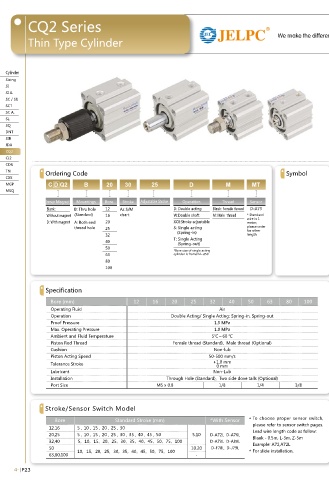
CQ2• Series CQ2• Series
We make the difference ISO9001:2008
Thin• Type• Cylinder Thin• Type• Cylinder
Overall• Dimension
Cylinder Cylinder
Sizing CQ2B• Ø10~Ø25 CQ2B• Ø32~Ø100 Sizing
SI SI
SI• A. SI• A.
SC• /• SU SC• /• SU
SCT SCT
SC• A. SC• A.
SL SL
SQ SQ
DNT DNT
SIB SIB
JDA JDA
CQ2
CQ2
CQ2 Double• Acting• Cylinder• Dimension• Chart CQ2
CJ2 CJ2
Bore/Symbol Stroke• Range• (mm) B ФD E F H C ФI J K L M ФN ФO P Q W Z
CDU CDU
12 5~30 17+st 6 25 5 M3x0.5 6 32 - 5 3.5 15.5 3.5 6.5• deep• 3.5 M5X0.8 7.5 - -
TN Ordering• Code Symbol 16 5~30 18.5+st 8 29 5.5 M4x0.7 8 38 - 6 3.5 20 3.5 6.5• deep• 3.5 M5X0.8 8 - 10 TN
CXS 20 5~50 19.5+st 10 36 5.5 M5x0.8 7 47 - 8 4.5 25.5 5.5 9• deep• 7 M5X0.8 9 - 10 CXS
MGP C D Q2 B 20 30 25 D M MT 25 5~50 22.5+st 12 40 5.5 M6x1.0 12 52 - 10 5 28 5.5 9• deep• 7 M5X0.8 11 - 10 MGP
MSQ 32 5 23+st 16 45 5.5 M8x1.25 13 60 4.5 14 7 34 5.5 9• deep• 7 M5X0.8 11.5 49.5 18 MSQ
10~50 7.5 1/8 10.5
40 5~50 29.5+st 16 52 8 M8x1.25 13 69 5 14 7 40 5.5 9• deep• 7 1/8 11 57 18
Inner• Magnet Mountings Bore Stroke Adjustable• Stroke Operation Thread Sensor 50 10~50 30.5+st 20 64 10.5 M10x1.5 15 86 7 17 8 50 6.6 11• deep• 8 1/4 10.5 71 22
•
Blank: B:• Thru• hole 12 • • • • • As• S/M• D: Double• acting Blank:• Female• thread D-A73 63 10~50 36+st 20 77 10.5 M10x1.5 15 103 7 17 8 60 9 14• deep• 10.5 1/4 15 84 22
•
80
104
•
Without• magnet (Standard) 16 • • • • • chart W:Double• shaft M:• Male• • thread *• Standard• 100 10~50 43.5+st 25 98 12.5 M16x2.0 21 132 6 22 10 77 11 17.5• deep• 13.5 3/8 16 123.5 26
10~50
53+st
17.5• deep• 13.5
11
3/8
26
23
94
M20x2.5
13
30 117
12
27 156 6.5 27
wire• is• 1•
D:• With• magnet A:• Both• end• 20 • • • • XC8:Stroke• adjustable meter,• • • • st=Stroke
•
thread• hole 25 • • • • S:• Single• acting please• order• Remark2)Long Stroke
•
for• other•
•
32 • • • • • • • • (Spring-in) length• Model Stroke(mm) B F P Q 1.• Standard• stroke• is• classified• every• 5• mm.
40 T:• Single• Acting 32 75,100 33 7.5 1/8 10.5 2.• 5,• 10,• 15• or• 20• mm• thick• gaskets• are• applied• on• stroke• from• • • •
• • • •(Spring-out)
50 40 75,100 39.5 8 1/8 11 • • • • 55mm• • to• 100mm• (55,• 60,• 65,• 70,• 80,• 85,• 90,• 95).
*Bore• size• of• single• acting• 50 75,100 40.5 10.5 1/4 10.5
63 cylinder• is• fromø12~ø50 63 75,100 46 10.5 1/4 15 3.• Unless• specified,• the• dimension• of• 4• holes• tapped• with• stroke•
80 80 75,100 53.5 12.5 3/8 16 • • • • length• cylinder• and• two• side• cover• talls• cylinder• are• the• same.
100 100 75,100 63 13 3/8 23
Single• Acting• Cylinder• st=Stroke
Bore/Symbol B ФD E F H C ФI J K L M ФN ФO P Q W Z
Specification 5st 10st 20st 5st 10st 5st 10st 20st 5st 10st
12 22 27 - 6 25 5 5 M3x0.5 6 32 - 5 3.5 15.5 3.5 6.5• deep• 3.5 M5x0.8 - 7.5 7.5 - -
16 23.5 28.5 - 8 29 5.5 5.5 M4x0.7 8 38 - 6 3.5 20 3.5 6.5• deep• 3.5 M5x0.8 - 8 8 - 10
Bore• (mm)• 12 16 20 25 32 40 50 63 80 100 20 24.5 29.5 - 10 36 5.5 5.5 M5x0.8 7 47 - 8 4.5 25.5 5.5 9• deep• 7 M5x0.8 - 9 9 - 10
Operating• Fluid Air 25 27.5 32.5 - 12 40 5.5 5.5 M6x1.0 12 52 - 10 5 28 5.5 9• deep• 7 M5x0.8 - 11 11 - 10
33
28
Operation Double• Acting/• Single• Acting:• Spring-in,• Spring-out 32 34.5 39.5 - - 16 45 7.5 7.5 M8x1.25 13 60 4.5 14 7 7 34 5.5 9• deep• 7 M5x0.8 1/8 - - 11.5 10.5 49.5 18
57
8
16 52
18
5.5
40
5
11
M8x1.25 13 69
14
8
40
9• deep• 7
1/8
11
Proof• Pressure 1.5• MPa 50 - 40.5 50.5 20 64 10.5 10.5 M10x1.5 15 86 7 17 8 50 6.6 11• deep• 8 - 1/4 10.5 10.5 71 22
Max.• Operating• Pressure 1.0• MPa
Ambient• and• Fluid• Temperature 5℃~60 ℃
Piston• Rod• Thread Female• thread• (Standard),• • Male• thread• (Optional) Overall• Dimension Both• ends• Single• Acting,• Spring-out• Ф12~Ф50
Cushion Non-lub Inner• thread• /CQ2A
Piston• Acting• Speed 50-500• mm/s Male• Piston•
Rod• Thread
Tolerance• Stroke +1.0• mm
0• mm
Lubricant Non-Lub
Installation Through• Hole• (Standard),• • Two• side• dove• talls• (Optional)
Port• Size M5• x• 0.8 1/8 1/4 3/8
Remark3)Both ends
Male• Piston• Rod• Thread Inner• thread Single• Acting,• Spring-out
Bore(mm) C X ФD H L K Bore(mm) O R Bore(mm) A L
Stroke/Sensor• Switch• Model 12 9 10.5 6 M5x0.8 14 5 12 M4x0.7 7 5st 10st 20st 5st 10st 20st
16 10 12 8 M6x1.0 15.5 6 16 M4x0.7 7 12 30.5 40.5 - 8.5 13.5 -
Bore Standard• Stroke• (mm) *With• Sensor * To• choose• proper• sensor• switch, • 20 12 14 10 M8x1.25 18.5 8 20 M6x1.0 10 16 32 42 - 8.5 13.5 -
please• refer• to• sensor• switch• pages.•• 25 15 17.5 12 M10x1.25 22.5 10 25 M6x1.0 10 20 34 44 - 9.5 14.5 -
12.16 5,10,15,20,25,30 Lead• wire• length• code• as• follow: 32 20.5 23.5 16 M14x1.5 28.5 14 32 M6x1.0 10 25 37.5 47.5 - 10 15 -
20,25 5,10,15,20,25,30,35,40,45,50 5.10 D-A72L• • D-A76L Blank-0.5m, L-3m, Z-5m 40 20.5 23.5 16 M14x1.5 28.5 14 40 M6x1.0 10 32 40 50 - 12 17 -
-
-
32,40 • • • 5,10,15,20,25,30,35,40,45,50,75,100 D-A73L• • D-A80L Example:• A72,A72L• 50 26 28.5 20 M18x1.5 33.5 17 50 M18x1.25 14 40 46.5 56.5 78.5 12 17 28
-
-
58.5
18
50
M10x1.5
26
50 10,15,20,25,30,35,40,45,50,75,100 10.20 D-F78L• • D-J79L * For• slide• installation. 63 32.5 28.5 20 M18x1.5 33.5 17 63 M12x1.75 18 *• Unless• Specified,• the• dimension• of• the• type• stroke•
M22x1.5
43.5
25
80
35.5
80
22
22
63,80,100 - 100 32.5 35.5 30 M26x1.5 43.5 27 100 M12x1.75 22 length• cylinder• end• two• side• cover• talls• cylinder• are •
the• same.
4-|P 23 4-|P 24