
Page 41 - 常州阿斯博开关有限公司
P. 41
型高压真空断路器
MVG-40.5 Type High Voltage Vacuum Circuit Breaker
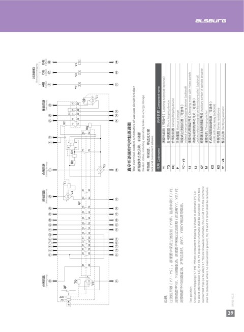
高压真空断路器电气原理图
Electrical Schematic Diagram of HV Vacuum Circuit Breaker
#ᄱ B phase 43 Y9 IὍ 44
B phase
I ǚ
B၎
44
43
Y9
ࡗୁྃ੩ Overcurrent tripping C၎ C phase 27 Y8 I ǚ 48 ืᑲ੮ Overcurrent tripping $ᄱ C phase 27 Y8 IὍ 48
A၎ A phase 2 Y7 I ǚ 37 "ᄱ A phase 2 Y7 IὍ 37
+ + V1
V1 M
M 元件名称 Component name 断路器主轴的辅助开关 Auxiliary switch of spindle breaker 用于试验位置的辅助开关 Auxiliary switch for test position ϲᑟڀ Tank circuit 25 21 22 元件名称 Component name 断路器主轴的辅助开关 Auxiliary switch of spindle breaker
ئీ࣮ୟ Tank circuit 25 21 22 - 闭锁电磁铁(可选件) Latching solenoid (optional) Indirect overcurrent tripping device (optional) 储能电机用微动开关 Charging motor with micro switch Locking electromagnet on the micro-switch (optional) S1 21 21 22 22 35 闭锁电磁铁(可选件) Latching solenoid (optional) Indirect overcurrent tripping device (optional) 储能电机用微动开关 Charging motor with micro switch Locking electromagnet on the micro-switch (optional)
21 21 22 22 35 Auxiliary switch for the working position 26 13 14 36
26 36 分闸脱扣器 Shunt tripping device 合闸脱扣器 Closing tripping device 间接式过流脱扣器(可选件) 闭锁电磁铁的微动开关(可选件) 机构内部防跳继电器(可选件) 24 S2 34 分闸脱扣器 Shunt tripping device 合闸脱扣器 Closing tripping device 闭锁电磁铁的微动开关(可选件) 机构内部防跳继电器(可选件)
24 13 14 34 手动储能 Manual storage 用于工作位置的辅助开关 储能电机 Charging motor Inside anti-hop relay (optional) 串联电阻 Series resistance 整流元件 Rectifying element 13 14 间接式过流脱扣器(可选件) Inside anti-hop relay (optional) 串联电阻 Series resistance 整流元件 Rectifying element
S2 13 14 The electrical control schematics of vacuum circuit breaker The circuit breaker status is opening, no energy storage, work location HQ The electrical control schematics of vacuum circuit breaker 手动储能 Manual storage 储能电机 Charging motor
HQ 53 54
S1 Breaker status, including separating brake, no energy storage
53 54 40
40 断路器状态为分闸、未储能、工作位置 1 4 2
1 真空断路器电气控制原理图 3 1 真空断路器电气控制原理图
4 2 带防跳、带闭锁、带过流方案 71 72 带防跳、带闭锁、带过流方案
3 1 lock and overcurrent scheme K0 断路器状态为分闸、未储能 lock and overcurrent scheme
71 72
K0 代号 Codename Y7~Y9 V1~V4 R0 V3 代号 Codename Y7~Y9 V1~V4
ࢇቄ࣮ୟ Closing the loop 4 R0 - + V3 14 Y1 TQ HQ P S1 S2 QF S8 S9 M KO RO Ռڀ Closing the loop 4 + 14 Y1 TQ HQ P S1 S2 QF M KO RO
33 34 Y1
29 73 74 39 81 82
Overcurrent tripping (Y7 Y9) : Where overcurrent tripping is shown in schematic (Y7 i.e:
Y1 QF V4
55 53 54 53 54 56 ᫇ᩚڀ Blocking Circuit 20 63 64 10
Կ࣮ୟ Blocking Circuit 20 - + V4 63 64 57 58 10 29 + QF 73 74 39
46 83 84 12 43 44 43 44 49 46 83 84 12
28 33 34 38 23 24 54 28 33 34 38
23 24 23 24 53
23 33 52 23 23 24 33
13 14
8 18 13 14 51 13 14 18
43 44 13 14 8
22 50 43 44
22
81 82 61 62
6 16 9 19
33 34 51 52
61 62 7 17
9 19 过流脱扣器(Y7~Y9):原理图中采用过流脱扣(Y7即:选用中间CT)时, 则原理图中Y8、Y9回路取消;原理图中采用2过流脱扣(即选用Y7、Y8)时, to select intermediate CT), the Y8, Y9 loop in the schematic shall be cancelled; where two overcurrent trips (ie to select Y7, Y8) are shown in schematic, the circuit Y9 in the schematic shall be cancelled; where no overcurrent is present, V7, Y8 and Y9 circuit shall be cancelled. 41 42 过流脱扣器(Y7~Y9):原理图中采用过流脱扣(Y7即:选用中间CT)时, 则原理图中Y8、Y9回路取消;原理图中采用2过流脱扣(即选用Y7、Y8)时, to select intermediate CT), the Y8, Y9 loop in the schematic shall be cancelled; where two overcurrent trips (ie to select Y7, Y8) are shown in schematic, the circuit Y9 in the schematic shall be cancelled; where no overcurrent is present, V7, Y8 and Y9 circuit shall be cancelled.
5 15 Overcurrent tripping (Y7 Y9) : Where overcurrent tripping is shown in schematic (Y7 i.e:
51 52 11 12
7 17 则原理图中Y9回路取消,不带过流时,则Y7、Y8和Y9回路均取消。 3 13 则原理图中Y9回路取消,不带过流时,则Y7、Y8和Y9回路均取消。
41 42 S8 S9 11 21 22 21
5 15
11 12
3 13
21 22 31 32
11 21
31 32 41
ݴቄ࣮ୟ Opening loop 30 QF TQ + - V2 31 ߾ፕ࿋ዃ work location ᄓ࿋ዃ Test position Ѭڀ Opening loop 30 QF TQ + V2 31
MVG- 40.5 OFF ON p 说明: Test position OFF ON p 说明: Test position MVG- 40.5
38 39